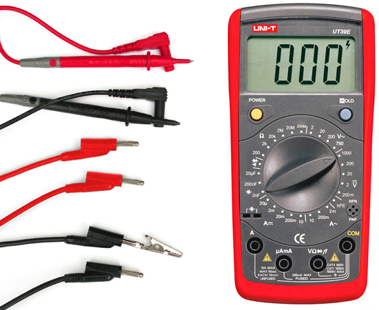
The digital multimeter (DMM) is an extremely versatile tool when diagnosing engine performance and troubleshooting electrical systems – combining the functions of many electrical measuring devices into one. Digital multimeters can measure voltage, electrical resistance, continuity, current, or test diodes in either direct current (DC) or alternating current (AC) with just a turn of a knob. In automotive applications, they can test the extent that wires, switches, fuses, relays, motors are conducting electricity properly. Top-of-the-line DMM’s can also use their abilities to read engine rpms and dwell as well as electrical duty cycle, frequency, pulse width, diode condition, and temperatures in some cases.
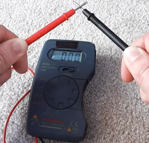
It’s a good idea to “recalibrate” your multimeter before using by touching leads to one another until a zero ohm reading is achieved. Some advanced meters have an automatic calibration feature.
Prior to digital multimeters with the ability to read volts, ohms, and amperes in tenths and hundredths, technicians relied on analog meters that featured a relatively imprecise needle gauge. Low internal resistance inherent on analog meters can allow too much current to pass through and cause problems with delicate electronic circuitry. In this article, we’ll cover the symbols multimeters use, how to do basic tests, and compare features found on a few different DMMs ranging in price from the low $20s to $50s.
Multimeters do not have heavy leads, so it’s important to make sure they don’t become overloaded and cause a blown fuse by selecting the proper scale on the dial. Higher end multimeters will typically have a greater range of scale choices. Once a test range scale has been picked out, positive and negative leads are connected to any circuit in the same way as individual (non-multi) meters would be.
UNDERSTANDING THE READINGS OF MULTIMETERS
Since DMMs typically display very large or small numbers, symbols will be used to clue the user if a number displayed (“5”, for example) should be multiplied by one-thousand or one-million if it represents five one-thousands or five one-millionths. Using the scale below, a DMM setting for mAmps will display milli-amps (or thousandths of an amp). Ohmmeter readings may use K where 5K ohms equals 5,000 ohms, or they may use M where 5M ohms equals 5,000,000 ohms. Multimeters with an “auto range” feature will automatically select the proper scale. Exponential prefix symbols used are:
M (Mega) = 1,000,000 (used for ohms readings)
K (Kilo) = 1,000 (used for ohms readings)
m (Milli) = .001 or 1/1,000th (used for amp and volt readings)
µ (Micro) = .000001 (1/1-millionth)
n (Nano) = .000000001
p (Pico) = .00000000001
Ω = The Greek alphabet symbol for Omega is used for ohms, or electrical resistance
A = Refers to amperes, or current flow
V = Refers to voltage, or the amount of electromotive pressure
A BRIEF COMPARISON OF THREE MULTIMETERS
To give you an idea how multimeters can vary, we’ve taken a look at three offerings at different price levels from one manufacturer. Most digital multimeters in all price ranges offer auto calibration between scale changes. Higher-end multimeters can add the ability to measure duty cycle, pulse width, and frequency which can be used to pinpoint when a circuit turns on or when voltage increases or decreases. They’ll typically allow the user to start a cycle count when voltage rises for monitoring activity of devices whose power feed is controlled by a computer, or when voltage drops to check components that are connected to a ground.
 Many digital multimeters also offer a HOLD button that records data such as minimum, maximum, and average voltage observed during a test. One benefit of this is the ability to track down troublesome electrical noise (also known as radio frequency interference) which causes voltage spikes and drops that interfere with computer controls.
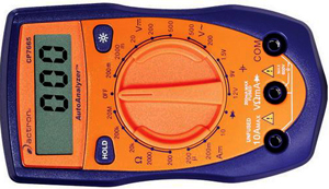
Actron Digital Multitester ($22)
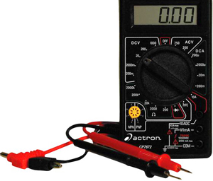 This digital multimeter includes the functions of an ammeter, voltmeter, and ohmmeter as well as the ability to measure AC voltage at any frequency. It has 19 ranges, a second set of leads that work like alligator clips, automatic polarity sensing, and auto-calibration to reset readings to zero between tests. For reference, meters without auto-calibration must be reset manually by holding the two test leads together and adjusting the meter reading to zero. This is a good multimeter for basic electrical testing rather than complex engine or computer module diagnosis.
 Actron Auto Analyzer ($32)
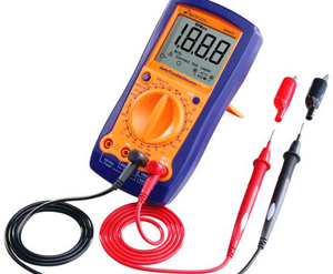
This digital multimeter offers the same benefits as the $22 model but adds convenience features such as a backlit LCD display and a portable stand.
 Actron Auto Troubleshooter ($52)
This is a full-service digital multimeter with 24 ranges instead of the typical 19. Benefits this model adds are the ability to test engine rpm and dwell. In addition to features found on the second DMM above, it also adds overload protection on all ranges, a hold button that retains data displayed, and audible tones.
TOP USES FOR MULTIMETERS:
Measuring Voltage (V)
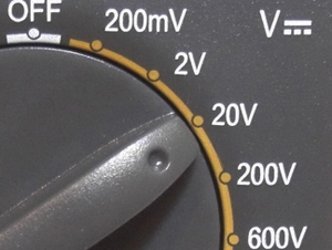 Choose a setting on your meter for DC or AC voltage. For automotive applications such as testing which wire is live when installing a headlight, stereo, or security system, use the DC voltage setting. Choose the right voltage range on your meter for what you expect to find – automotive applications being 12 volts and household applications being 120 volts. Ground the negative lead by touching it to a bare metal component on the vehicle that isn’t painted or rusted. Touch the positive lead to the wire or wires that you are testing. If you don’t know what the voltage is that you’ll be checking, choose the highest range and work your way lower until you get a reading. When checking a bulb socket to see if it’s getting power, touch one probe to the side of the bulb socket and touch the other to the tip at the bottom of the socket.
 Multimeters with an autorange function do not require you to select the voltage you’re measuring. Observing polarity with your leads is only important when measuring DC voltage or millivoltage, not AC voltage. When measuring AC voltage, the “Root Mean Square” (RMS) setting will convert the signal to a comparable DC one, and an “Average Responding” setting will display and average of the voltage peak amounts.
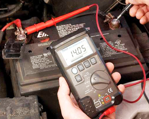 If you’ve been having issues with your charging system, a quick test of the battery and charging system will pinpoint the problem. First, check the battery itself without the engine running by touching positive and negative multimeter leads to corresponding battery posts. If the voltage of a standing battery is less than 12 volts, the battery itself is no longer functioning well and should be replaced. If the battery is healthy, start the engine and monitor the voltage with the leads still on the battery posts. With all accessories off, optimal voltage of a properly functioning alternator ranges from 13.7 to 14.9 volts. A low voltage reading at this point signifies a problem with the alternator or the wiring between the alternator and the battery. A high voltage reading of 17 or 18 volts signifies the alternator is defective and overcharging the battery.
Measuring Continuity
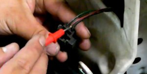
 If you’re checking to see if a fuse or relay on your vehicle is good or bad, you’ll want to check continuity between the end of the circuit where power goes in and the end where it goes out. Select the Ohms setting on your meter, and place leads on either side of the fuse or relay contact points you’re checking. Positive and negative polarity doesn’t matter here because results will be the same either way – a low ohms reading means continuity is good and your fuse or relay is working.
If you need to check a circuit or wiring to see if an open exists (and electrical flow is broken), a continuity test will be performed. A reading of infinity means that the circuit is open and cannot conduct electricity while a reading closer to zero means the circuit is complete and can conduct electricity.
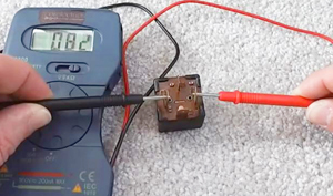 To test if a switch is faulty, touch the tester leads to both poles on the switch. Turning the switch being tested from off to on should change the multimeter’s reading from infinity to zero if the switch is working properly. If you’re checking an electrical motor in this fashion, a reading slightly above zero confirms enough continuity exists within the motor for current to pass through easily.
Measuring Resistance
 Connect multimeter leads to the circuit being tested, making sure the red probe is in the terminal for measuring ohms and volts and the black probe is placed in the common terminal. Turn the selector knob to measure ohms of electrical resistance. Shut off power to the circuit and remove the resistor that’s to be measured to ensure accuracy. Touch probe tips against opposite sides of the resistor and check the readings. Good continuity will result in zero or near-zero ohms while a circuit that’s blocked by a lot of resistance will show an infinite reading in the form of a blinking “OL”, “1.000”, or “1”.
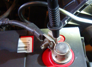 This test is useful for finding a metal part on your vehicle that can be trusted to use as a grounding point that won’t conduct any electricity. With the selector on ohms, touch the negative lead to the negative battery post, then touch the positive lead to the unpainted metal on your vehicle you want to check. The meter will read maximum resistance when electricity cannot be conducted, and you’ll see the infinite “OL” reading referenced in the last paragraph.
Measuring Current
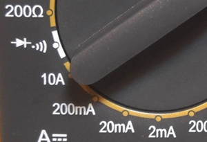 To obtain an exact current reading, set the multimeter to “A” for current. Best choices to use are either 10amps if dealing with a higher amount of current, or 300 milliamps (mA) if you’ll be tracking lower amounts of electrical flow. Touch positive and negative leads to corresponding sides of the circuit, then turn on the power. Current will flow first into the circuit, through the red lead, through the multimeter, and back to the circuit through the black lead. At this point, you’ll get a reading on the display.
Testing Diodes
 Testing diodes involves running current through the diode in both directions to test forward bias as well as reverse bias. First, connect the positive probe into the terminal marked for measuring volts, ohms, or diodes. The negative probe should go into the common terminal.
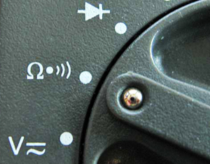
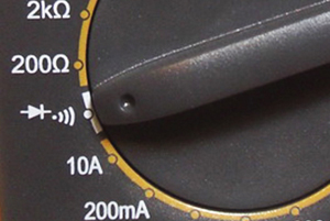
Turn your multimeter’s knob to the diode test setting, usually marked by a symbol showing an arrow pointing at a vertical line. Test forward bias first by touching the red lead to the positive side of the diode and the black lead to the negative side. Readings greater than zero but less than 1 indicate good forward bias. To test reverse bias, switch the red and black probes to the opposite sides of the diode and look for a reading of “OL” (overload) to signify reverse bias is good. If you should get readings of zero or “OL” while performing a forward bias check along with a zero reading during reverse bias check, the diode is bad.