An air conditioning manifold gauge set is a must-have tool for anyone who’s checking pressure in a/c lines, determining if there’s a leak, evacuating the entire system before making any repairs, or recharging with new refrigerant. Compact, hand-held manifold gauge sets are used universally when servicing home air conditioning systems as well as automotive ones, and professional technicians use them same way you can in your back yard. Although shops typically have large, costly machines that do the evacuating and recharging work, the same results can be achieved with relatively inexpensive equipment that can be held in your hands and stored easily.
 TOOLS NEEDED:
-The air conditioning manifold gauge set itself
-Kit with universally sized compression fittings that adapt and connect manifold gauge line ends to your vehicle
-R-134a refrigerant canister with a/c system dessicant oil
-Open ended wrench set
Since it’s common for a/c refrigerant to work its way out of the system over a few years when small leaks (or even no leaks) are present, an a/c manifold gauge will allow you to give your system a full charge each year – keeping your vehicle cool while saving you a great deal of money over a lifetime. A manifold gauge set can also let you determine if your system is fully charged or low, and if your system is losing pressure at a rate that indicates there’s a large leak. Even if you won’t be servicing the system yourself, it will be easy to determine whether you need repairs or just a recharge.
One of the basics to know before using an a/c manifold gauge set is the type of refrigerant that your vehicle has. For reference, refrigerant type R-12 was used from the earliest days of automotive a/c systems until the U.S. government outlawed it after the 1993 model year because of its harmful effect on the Earth’s ozone layer. While some vehicles made a switch to newer R-134a refrigerant before they were required to, any 1994-on model year vehicle sold in the United States was designed to operate on R-134a. Fittings on a/c systems with the two different types of refrigerants are different, so it’s important to know what you need.
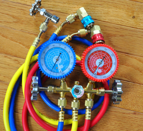
A closeup of a typical a/c manifold gauge set. The blue hoses, gauge, and valve knob represents the low pressure side of the air conditioning system, and red ones represent the high pressure side. The yellow hose in the center is designed specifically for recharging the system with canned refrigerant, and evacuating the system.
A sticker mounted on a cross-member directly under hood will provide the refrigerant type, but if it’s missing you’ll also find the information in the owner’s manual or by calling the vehicle manufacturer. If an older vehicle has been converted to R-134a, a new sticker stating so should be affixed in place of the original one. Additionally, the two types of refrigerant should never be mixed. In this article, we’ll focus on the simple basics of how to use an a/c manifold gauge set to check your system pressure, determine if large leaks in the system exist, and we’ll cover how to evacuate and recharge your system. Because R-12 is no longer readily available on the marketplace, we’ll focus on systems designed for R-134a. Should you be unable to determine which type of refrigerant your vehicle is equipped for, universal manifold sets with fitments for both systems are available.
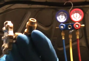
Shown at the ends of low- and high-pressure lines in this photo are “manual” coupling pieces. Blue or red colored discs atop each must be depressed by hand to fasten or release the couplers.
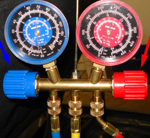
Looking at any a/c manifold gauge, you’ll see a blue-colored pressure dial and hose on the left side, a red-colored pressure dial and hose on the right, and a yellow hose in the middle with no corresponding dial. Blue represents the low pressure side of the air conditioning system, and red represents the high pressure side. The low-side gauge is also known as a compound gauge because it can also provide a reading for vacuum pressure (expressed in “inches of mercury”) that’s built up in the entire system. The yellow hose in the center is designed specifically for refilling the a/c system with canned refrigerant during recharging, and it can also be used for evacuating the system with a vacuum pump.
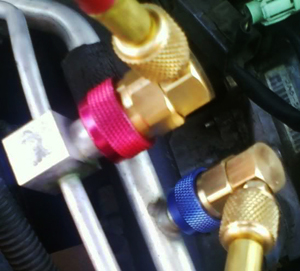
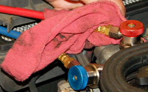
Shown at the ends of low- and high-pressure lines in this photo are “automatic” coupling pieces after being connected to a vehicle’s a/c system. Blue or red colored lock rings on the couplers lock in place automatically during fastening, then release when slid upward by hand.
Hoses on a/c manifold sets connect and disconnect to fitments on the vehicle easily with Schrader style valve couplings. Some hoses are designed with “manual” couplers that feature a quick release button on top which must be depressed manually to lock the connection in place, and other hoses are designed with “automatic” couplers which click into place with a simple push. Instead of using a pushbutton to release, a lock ring is moved by hand.
TESTING THE PERFORMANCE OF YOUR A/C
 Before doing anything else, a quick pressure test of your vehicle’s a/c system with it running will give you an idea if operating pressures are within specifications. After closing both low- and high-side valves on the manifold gauge set, connect hoses to respective low- and high-side pressure fittings on the vehicle. Start your engine and run the a/c system at full blast until it’s had time to cool the inside of the car. Open the valves on the manifold set then check high and low pressures on the dials, comparing them to the normal range of the operating pressure specified in your owner’s manual or repair guide.
Excess high-side pressure can result from too much refrigerant in the system, a restriction, air in the lines, or not enough airflow across the condenser. Low high-side pressure can mean refrigerant level is low or the compressor is malfunctioning. If the low-side pressure is higher than normal, suspect refrigerant overcharge or a defective compressor. Lower low-side pressure can result from a restriction in the low-side of the system, the refrigerant level is low, or not enough airflow across the condenser behind the front grille.
EVACUATING THE A/C SYSTEM
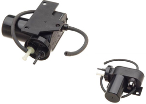
Before doing any repairs or recharging a vehicle’s a/c system, all old refrigerant, air, moisture, and contaminants must first be evacuated. This can be done in easily in the convenience of your driveway with a compact electric vacuum pump (shown above) designed specifically for automotive a/c systems.
Evacuating the system with a vacuum pump is optional if you’re simply looking to top off your system with refrigerant. To obtain an exact scientific measurement of how large your leak is, it’s necessary. Should you opt to perform that operation, you’ll need a compact electrical vacuum pump designed for automotive a/c systems. The process begins by twisting both low- and high-side valves on the manifold gauge set to the closed position (both on the gauge housing and at the hose ends), then connecting the hoses to respective low- and high-side pressure fittings on your vehicle. Once hoses are connected to vehicle fittings, open the valves where they attach to the vehicle.
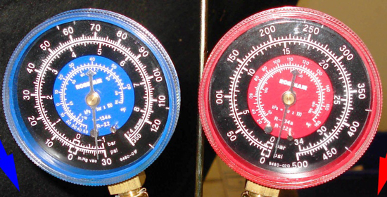
Only the low-pressure side gauge has a reading for vacuum. When the system is being evacuated, the needle will travel to the right of zero to reflect negative pressure (vacuum) in the lines as shown here. If the system holds vacuum pressure without dropping for 30 minutes after being evacuated, there are no large leaks in the system.
Next, connect the yellow hose to your vacuum pump and turn it on. Once it’s running, open the low and high-side valves on the manifold gauge set housing. Let the pump run for approximately 30 minutes to an hour until you see the low-side dial displaying a vacuum pressure of 30 inches of mercury. The high-side gauge needle will remain at zero the entire time. Once proper vacuum pressure has been reached, close both high and low-side valves and shut the pump off. If vacuum pressure holds for 30 minutes once the pump is shut off, the system does not have any large leaks anywhere.
A decline in pressure means there’s a large leak somewhere, or water in the system has boiled off. To determine which is the case, repeat the evacuation process for 30 minutes with the pump, then let it sit again for another 30 minutes. If the pressure declines again, the only possibility at this point is a large leak in the system.
RECHARGING YOUR A/C SYSTEM
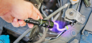
In this picture, an ultraviolet flashlight is being used to detect the presence of leak tracing dye in an air conditioning system. Areas where the dye has leaked out of the system can be determined because the dye is designed to glow when subject to UV rays.
Whether you have a large leak or want to test for a small leak that could take longer to show up, adding leak tracing dye when recharging the system is recommended. By the time you notice your a/c starts blowing warm air again, enough refrigerant and leak tracing dye have leaked out to be visible under a black light. Of course, if it turns out your system has no leaks, you’ll continue to enjoy cold air coming out of your vents indefinitely.
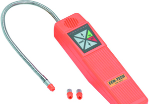
Shown here is an electronic leak detector that can also be used to detect the presence of refrigerant that has escaped outside the a/c system.
To recharge your a/c system, insert a valve in the tank or can of new refrigerant you’ll be using (you may need a wrench for this process depending on the valve design). Make sure the can and the valve knob are facing up to ensure you’ll be drawing refrigerant vapor from the top of the can instead of liquid refrigerant from the bottom. The valve knob should also be in the closed position before installing it on the refrigerant container.
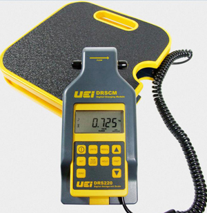
Precise accuracy when recharging an a/c system is extremely important. To ensure the correct amount of refrigerant gets added, it’s recommended to put your refrigerant can/tank on top of a finely-tuned refrigerant scale. As refrigerant leaves the container, the scale calculates the weight.
For precise accuracy, place the refrigerant container on top of a refrigerant scale. This is a finely-tuned scale that lets you know exactly how much refrigerant has been moved out of the can into your vehicle, by weight. If your vehicle needs one and a half cans of refrigerant, for example, this scale will save you from guessing when you’ve depleted half of the second can. It’s important to add the exact amount your vehicle manufacturer specifies because too little refrigerant will make your a/c system ineffective, and too much refrigerant will cause system-damaging pressures.
With the valve knob closed on the refrigerant canister, connect the yellow hose from the a/c manifold gauge set. With the line connected, open the valve on the tank. After that, the next step in the procedure is to bleed air out of the yellow line so that it does not get pushed into the a/c system. Do this by loosening (but not disconnecting) the yellow hose fitting at the top of the manifold gauge set until you hear air hiss out for two seconds.
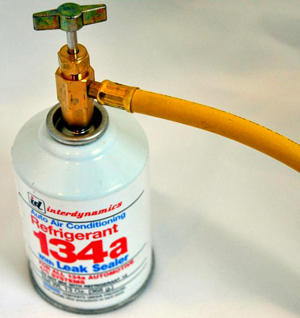
In this photo is a portable can of R-134a refrigerant that’s been mandated by the U.S. government since the 1994 model year. When using a portable can or tank to recharge your system, make sure both the container and the valve knob are facing up as shown here. This ensures you’ll be drawing refrigerant vapor from the top of the can instead of liquid refrigerant that may be at the bottom.
Once air is bled, open low- and high-side valves on the a/c manifold housing. Refrigerant will now pass from the canister to your vehicle’s a/c system until the pressure in the tank drops to the same level as your a/c system. To suck more refrigerant out of the canister, start your vehicle after closing both low- and high-side valves. Open only the low side valve and watch for a decrease in low-side gauge pressure with an increase in high-side pressure. When this occurs, pressure vacuum in the low side will pull more refrigerant into the system. Caution – opening the high side valve when the a/c compressor is running will damage the compressor.
When the scale indicates you’ve transferred the proper amount of refrigerant by weight, close the low-side valve on the manifold gauge set. Turn the valve on the canister off, then disconnect your yellow hose. Finally, disconnect charging lines attached to fittings on the vehicle. Your a/c system is now fully charged.
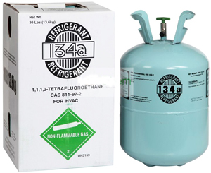
R-134a refrigerant is also sold in portable tanks.